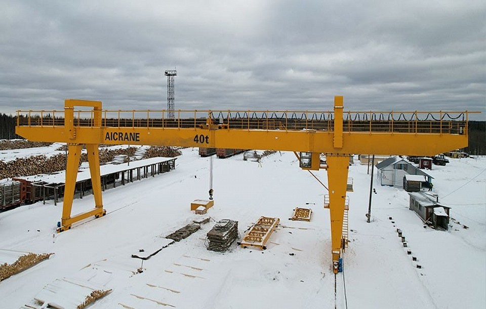
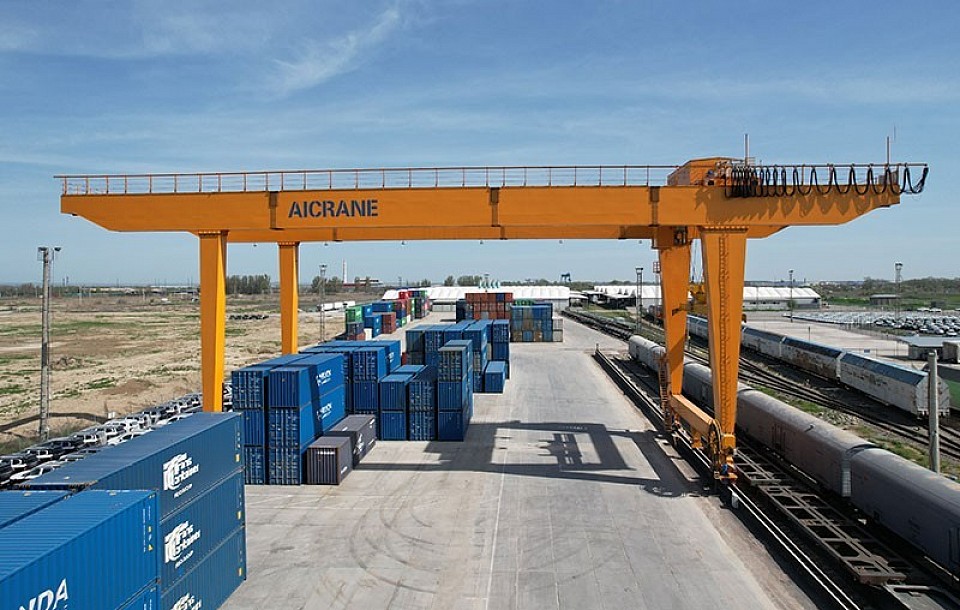
Understanding Gantry Crane Capacity
Gantry cranes are critical assets in industries ranging from shipping ports and steel plants to construction sites and manufacturing facilities. As operational demands increase - due to heavier loads, larger components, or higher throughput - there is a growing need to enhance the capacity of existing gantry cranes or design new cranes with higher load ratings. Increasing gantry crane capacity is not a simple matter of scaling up size; it requires careful structural design considerations to ensure safety, durability, and efficiency. This article explores the key structural factors involved in increasing gantry crane capacity, providing guidance for engineers, designers, and operators.
The capacity of an industrial gantry crane refers to the maximum load it can safely lift and move. Capacity depends on multiple elements including structural components (girders, legs, end trucks), hoisting mechanisms, control systems, and the foundation supporting the crane. Increasing capacity affects each of these elements and often requires a comprehensive approach rather than isolated upgrades.
Key Structural Design Challenges in Increasing Capacity
1. Strengthening Primary Structural Components
The crane’s main structural elements - typically the girders, legs (columns), and end trucks - must be engineered to safely carry increased loads and resist associated stresses.
1.1 Girder Design and Material Selection
The girder is the primary horizontal beam supporting the trolley and hoist. Increasing crane capacity means girders will experience greater bending moments and shear forces.
Cross-Section Optimization: Larger or deeper girders increase the section modulus, enhancing bending resistance. Designers often switch from I-beams to box girders or truss girders for higher stiffness-to-weight ratios.
Material Strength: Using higher-grade steel with improved yield strength (e.g., ASTM A992 or A572 grade 50) can increase capacity without significantly increasing weight.
Fatigue Resistance: For cranes with high duty cycles, girder design must consider fatigue stresses over time to avoid premature cracking.
1.2 Leg and End Truck Reinforcement
Legs transfer loads to the crane wheels and foundation, so they must resist axial compression, bending, and buckling.
Increased Sectional Area: Enlarging leg cross-sections or adding reinforcing plates improves load capacity.
Buckling Prevention: Introducing internal bracing or using box sections can enhance buckling resistance.
End Truck Strength: End trucks must accommodate heavier wheel loads and bending moments; redesign often includes stronger beams and wheels rated for higher loads.
2. Addressing Dynamic and Impact Loads
Increased capacity cranes are subject not only to higher static loads but also elevated dynamic loads due to acceleration, braking, and load sway.
Dynamic Load Amplification: Designers must factor dynamic load factors (typically 1.2 to 2 times static load) into structural sizing.
Shock Absorbers and Sway Control: Structural designs may integrate anti-sway mechanisms, shock absorbers, and damping systems to reduce dynamic stresses.
Robust Connections: Welds, bolts, and joints must be designed to resist fatigue and impact loading over time.
3. Enhancing Stability and Rigidity
Higher capacity cranes require greater stability to prevent excessive deflections, sway, and potential tipping.
3.1 Lateral Stability
Bracing Systems: Cross-bracing between legs and girders adds stiffness against lateral loads such as wind or crane acceleration.
Wider Base Spans: Increasing the span between legs improves the base stability but also demands stronger girders.
Foundation Design: The foundation must be upgraded or redesigned to handle increased reaction forces without settlement.
3.2 Vertical Deflection Limits
Deflection limits ensure that the crane remains within safe operating parameters, preventing structural damage and operational hazards.
Girder Stiffness: Optimizing moment of inertia to minimize deflections.
Use of Trusses: Truss girders can provide high stiffness with reduced weight.
Advanced Materials: In some cases, composites or high-strength alloys are considered to improve stiffness-to-weight ratios.
4. Wheel Load and Rail Considerations
Increasing capacity translates to higher loads on crane wheels and rails, influencing structural design.
Wheel Load Distribution: Structural design must ensure even load distribution to avoid overstressing individual wheels or rails.
Wheel Material and Size: Upgrading wheels to larger diameters or stronger materials reduces contact stresses.
Rail Quality: Rails must be checked and possibly upgraded to withstand higher wheel loads without deformation.
5. Hoisting and Trolley Structural Integration
The hoist and trolley assembly are critical for load handling, and their structural integration with the crane girder is essential.
Trolley Beam Strength: The trolley beams must support heavier hoisting equipment and loads.
Reinforced Hoist Mountings: Structural reinforcements where hoists attach to girders prevent localized stress concentrations.
Control of Load Pendulum Effect: Structural design and control systems must minimize the swinging of loads during movement.
Design Methodologies and Standards
Use of Finite Element Analysis (FEA)
Finite Element Analysis has become a standard in modern crane design to simulate stresses, deflections, and dynamic behavior.
Modeling Complex Loads: FEA allows detailed modeling of static and dynamic loads, including impact forces and wind.
Optimization: Engineers can optimize cross-sections and materials to balance strength and weight.
Failure Mode Identification: Potential weak points or fatigue hotspots can be identified early.
Compliance with International Standards
Designs must comply with relevant standards such as:
CMAA Specification 70 and 74 (Crane Manufacturers Association of America)
ASME B30.17 (Overhead and Gantry Cranes)
ISO 4301-1 (Classification of Cranes)
EN 15011 (European standard for overhead cranes)
These standards provide guidelines on load factors, safety margins, testing, and inspection criteria essential for high-capacity crane design.
Practical Considerations for Increasing Capacity
Retrofitting Existing Cranes
Upgrading the capacity of existing gantry cranes involves:
Structural Reinforcements: Adding plates, stiffeners, or strengthening joints.
Replacing Components: Installing higher strength girders, legs, or wheels.
Load Testing and Certification: Revalidating capacity after modifications with load tests.
Retrofitting is often more cost-effective than purchasing new cranes but requires detailed structural assessment.
Cost and Material Efficiency
While increasing capacity generally increases material usage and cost, efficiency can be improved by:
Optimized Structural Forms: Using trusses, box sections, or cellular beams.
High-Strength Materials: Reducing section size but increasing strength.
Modular Designs: Facilitating easier maintenance and future upgrades.
Conclusion
Increasing the capacity of gantry cranes is a multifaceted engineering challenge that demands careful structural design considerations. From strengthening girders and legs to managing dynamic loads and ensuring lateral stability, every aspect of the crane’s structure must be carefully engineered to handle heavier loads safely. Advances in materials, design tools like finite element analysis, and adherence to international standards have made it feasible to develop high-capacity gantry cranes that meet modern industrial demands. Whether designing a new single or double girder gantry crane or upgrading an existing one, a holistic approach that balances strength, stiffness, cost, and operational safety is essential.
By understanding and addressing these structural design factors, engineers and operators can successfully increase gantry crane capacity, enhancing operational efficiency and extending the service life of these indispensable machines.
